
The Poor Man’s Oscilloscope
For the stereo photographer with an electronics background
During the development of electronic projects there are times when one needs to make some timing measurements. The best way to achieve accurate measurements and visualise those “invisible” electronic circuits is to use an oscilloscope. Unfortunately, oscilloscopes are expensive.
But fortunately, there are other possibilities to explore for simple oscilloscope functionality. One good example is an article from the internet authored by Rob Crocket. The tittle of the article is “Poor Man’s Oscilloscope: using a computer with a sound card as an oscilloscope”.
The basic concept is to use the audio line input of a sound card to capture measurements. The signals can then be recorded and analysed using audio editing software.
It is important to point out that this solution has several issues. The big caveat is that a sound card can only capture low voltage alternating current signals and not direct current signals! It is also not so easy to measure the absolute voltages of the signals. So, if you are prepared to put up with these limitations then this could be the inexpensive solution for you.
The diagram below shows the circuit details to construct a simple interface for connection to a computers sound card. The circuit is basically similar to Rob’s original circuit with some important changes/additions. Firstly, the resistor values forming the voltage divider are transposed to further reduce the signal level. Secondly, back to back diodes have been added so that accidental exposure to higher voltages does not destroy the sound card! The addition of diodes in the circuit serve to “clamp” the maximum voltage entering the sound card to about 0.7 volts. The inclusion of the diodes in the design came through painful experience after destroying three sound cards!
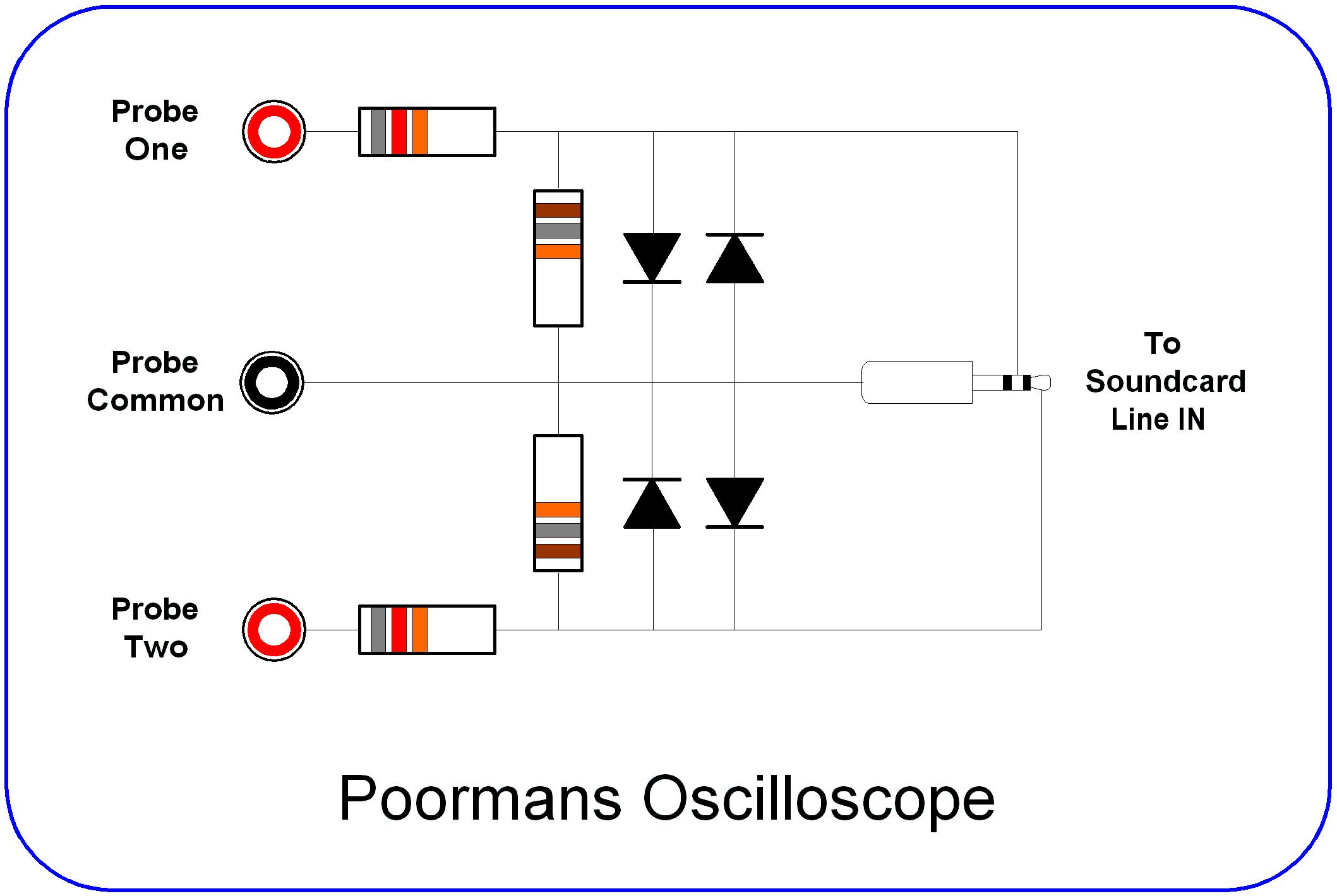
Parts List:
2 x 82KΩ and 2 x 18KΩ resistors - wattage rating not significant
4 x IN4007 silicon power diodes
Suitable connectors - for probes and connection to sound card
Once the hardware has been constructed, then it’s time to try it out. But first you must load an audio editor on your computer. One of the best editors for the task is Audacity® which is free open sourced software. The software can record a stereo track allowing measurement of two signals independently. The versatility of the Audacity® GUI interface provides facilities to make very selective timing measurements. The timing measurements accuracy is only limited by the sampling rate of the sound card.
To demonstrate the Poor Man’s Oscilloscope, a probe was connected to a Ricoh CA-1 remote camera shutter release. This remote release is used by Stereo Data Maker for stereo camera rigs. The remote outputs a series of 5volt pulses. The pulses are made up of various widths from 30mS to 150mS. For example, the “focus” signal from the CA-1 is represented by a single 30ms pulse. A sample measurement is shown below.
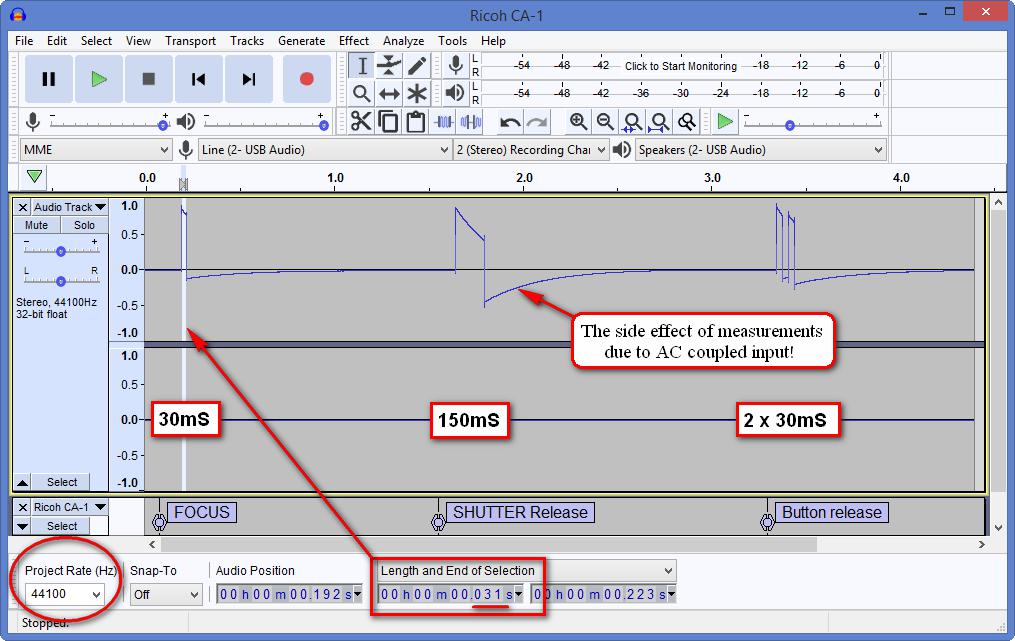
Screen shot from Audacity showing Ricoh CA-1 camera remote measurement
This screenshot displays the best and the worst characteristics of the poor man’s oscilloscope!
The AC coupled input of the sound card cannot truly represent the 5volt DC signals from the CA-1. The output of the CA-1 on a traditional oscilloscope would be displayed as a square wave, not the sawtooth looking waveform recorded by Audacity.
The prime benefit offered by Audacity is the ability to make selections of signal components and measure the time duration. The screenshot shows a selection of the “focus” signal.
The timing accuracy is ultimately determined by the sampling rate of the sound card. The sampling rate for the measurement shown in the screenshot is 44.1KHz.